Plinth
A line-following robot for my mechatronics class. It should follow black electri…
by QA Tester - Colorado School of Mines
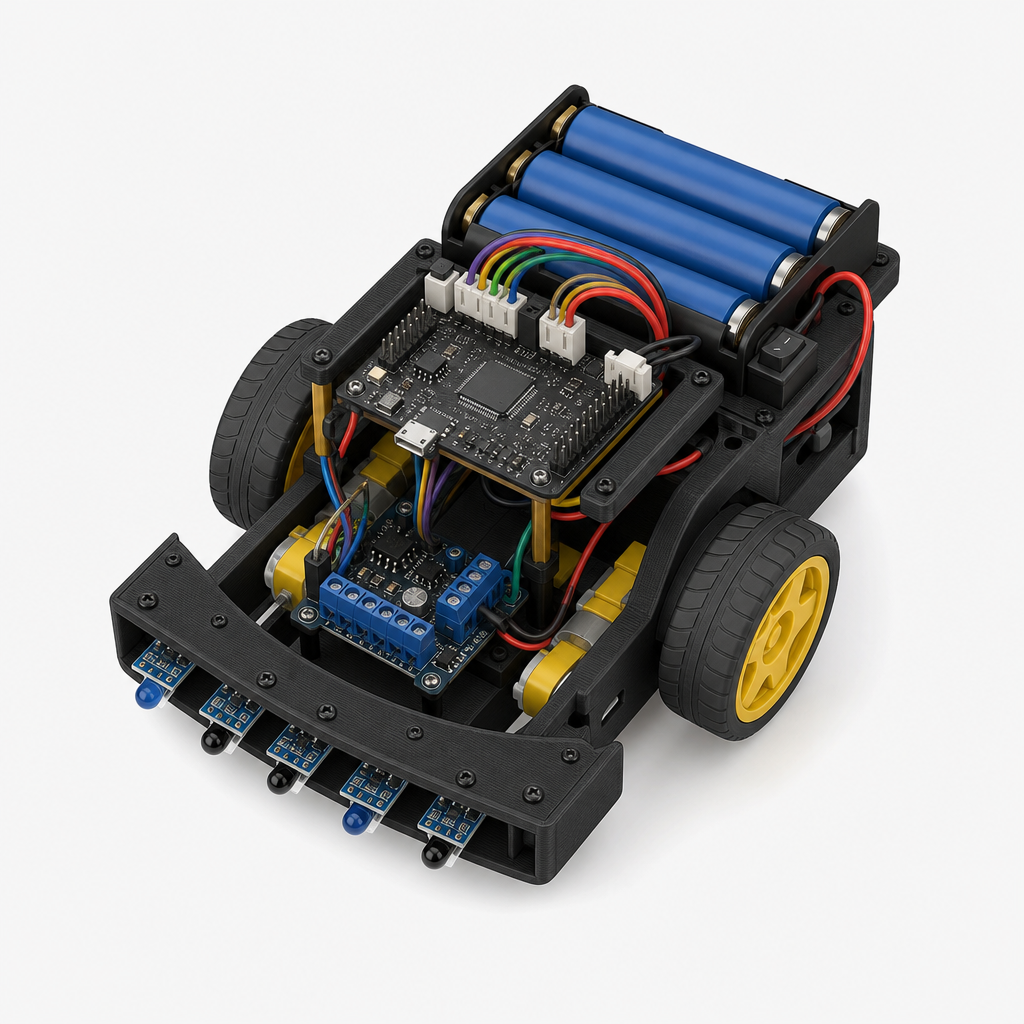
A line-following robot for my mechatronics class. It should follow black electrical tape on a white floor, handle 90-degree turns, avoid an obstacle, and finish a 20m course in under 60 seconds. Budget around $80. I have access to a 3D printer and a basic soldering station.
◢Bill of Materials
Sensing
IR reflectance sensor array for line detection and ultrasonic sensor for obstacle avoidance
Actuation
Dual DC gearmotors and motor driver IC for differential drive locomotion
Structure
3D-printed chassis, wheels, caster, and mechanical fasteners for the robot body
3D-Printed Robot Chassis (PLA filament, approx 150g)
other
CHASSIS-3DP
65mm Rubber Drive Wheels (pair, fits FIT0450 shaft)
other
WHEEL-65MM-PAIR
Ball Caster (rear wheel, 3/8 inch stainless steel ball)
other
CASTER-3/8
M3 Screw & Nut Assortment (stainless steel, 100-piece for mounting all PCBs and brackets)
other
M3-ASSORT-100
Power
Battery pack and voltage regulation to supply 5V logic and 6-7V motor rail
100uF 25V Electrolytic Capacitor Radial TH (Power Decoupling)
digikey
860010473007
4×AA Battery Holder (6V, enclosed with switch and wire leads)
other
BH-4AA-SW
L7805CV 5V 1.5A Linear Voltage Regulator TO-220
digikey
L7805ABV
Compute
Arduino Nano-based microcontroller running PID line-following algorithm, obstacle detection logic, and motor control output
Total: $77.76 USD
◢Build Schedule
14-week plan
All parts ordered, Arduino IDE + libraries installed, GitHub repo initialized
Order every component today — pay special attention to long-lead items: 3D-Printed Chassis (PLA, ~150g), 65mm Rubber Drive Wheels, Ball Caster, M3 Screw & Nut Assortment, and 4×AA Battery Holder. While waiting for parts, install Arduino IDE, add the Pololu QTR library and DRV8833 examples, and create a GitHub repo with a README skeleton for your written report.
You’ll need to know · 1
- Basic Arduino IDE usage
QTR-8RC reads all 8 channels; calibration routine verified on bench
Parts are in transit — use this week to deeply learn the QTR-8RC: wire it to the Nano Every on a breadboard, run the Pololu example calibration sketch, and read raw + calibrated reflectance values over Serial Monitor. Confirm all 8 channels respond to black tape vs. white paper. This sensor knowledge is the foundation of your PID error signal — getting it right now saves hours later. Double-check that all long-lead orders (chassis, wheels, caster, M3 hardware, battery holder) have confirmed ship dates.
You’ll need to know · 2
- Arduino digital/analog I/O and Serial Monitor - Getting Started with Arduino ↗
- Breadboard wiring and basic circuits
DRV8833 drives both motors at variable speeds from Nano PWM; direction verified
Learn the DRV8833 dual H-bridge by wiring it on the breadboard with the two FIT0450 gearmotors and the 4×AA battery pack (6V motor rail), regulated to 5V logic via the L7805CV. Write a simple test sketch cycling through forward, reverse, and differential turns on both motors. Use your multimeter to confirm voltage rails and the oscilloscope to verify PWM duty-cycle signals on the motor inputs — this is where your lab equipment pays off early.
You’ll need to know · 3
- PWM output with analogWrite() on Arduino - Arduino PWM / analogWrite ↗
- H-bridge motor driver concepts
- Voltage regulator wiring and decoupling capacitors
HC-SR04 returns accurate distances 5–100 cm; obstacle detection logic written
Wire the HC-SR04 ultrasonic sensor to the Nano Every and write a clean, non-blocking distance measurement function using pulseIn(). Verify accuracy against a ruler at 10, 20, 30, and 50 cm with your multimeter timing reference. Then write a threshold-based obstacle detection state: if distance < 25 cm, set an OBSTACLE_DETECTED flag. This prepares the avoidance logic module independently before integrating it with line-following later.
You’ll need to know · 2
- Arduino digital I/O and pulseIn() - Getting Started with Arduino ↗
- Finite state machine design basics
Chassis fully assembled: motors, caster, wheels, all electronics mounted
By now all long-lead hardware should have arrived. Print any supplemental brackets or sensor mounts in PLA (allow ~4 hours print time). Bolt the FIT0450 motors into the chassis, press-fit the 65mm wheels, install the ball caster at the rear, and secure the Nano Every, DRV8833, and QTR-8RC sensor array with M3 screws. Mount the HC-SR04 at the front center. Route and zip-tie all wiring, keeping motor power and logic power lines separated to reduce noise.
You’ll need to know · 2
- Basic soldering (headers, through-hole components) - Adafruit Soldering Guide ↗
- 3D printer operation and slicing (PLA settings)
Robot follows straight line and curves with bang-bang control on real floor
Before tuning PID, establish a working baseline using simple bang-bang (on/off) control from the QTR-8RC position estimate. Place the robot on your actual test surface (white floor, black electrical tape) and confirm it tracks a straight line and a gentle curve without losing the line. This validates sensor mounting height, motor polarity, and chassis geometry — all of which must be correct before PID will converge. Log the error signal to Serial for later analysis.
You’ll need to know · 3
- QTR-8RC calibration and readLine() API (covered Week 2)
- Motor PWM control via DRV8833 (covered Week 3)
- Differential drive steering logic
PID controller implemented; robot tracks line at target speed, Kp/Ki/Kd tuned
Replace bang-bang with a full PID loop: compute proportional error from QTR readLine(), integrate it over time, and differentiate for damping, then map the output to left/right motor speed differential. Start by setting Ki=Kd=0 and tuning Kp alone, then add Kd to reduce oscillation, and finally a small Ki to eliminate steady-state offset. Log all three terms and the setpoint over Serial, and use the oscilloscope to watch PWM signals stabilize. Target smooth tracking at 40% throttle before pushing speed.
You’ll need to know · 2
- PID control theory (P, I, D terms and tuning)
- Bang-bang baseline working (Week 6)
Robot reliably handles 90-degree left and right tape turns without losing line
Ninety-degree turns stress-test your PID because all sensors briefly go dark mid-turn. Implement a "lost-line" recovery state: detect when readLine() returns an all-dark or all-light reading, then execute a timed pivot in the direction of the last known error, and re-acquire. Test at least 10 consecutive left and 10 consecutive right turns on a real tape course. Adjust QTR sensor height and PID gains if needed; 90° handling must be rock-solid before adding obstacle avoidance on top.
You’ll need to know · 2
- PID line-following loop working (Week 7)
- Finite state machine implementation in Arduino C++
Obstacle detected, bypassed, and line re-acquired in under 8 seconds
Integrate the HC-SR04 obstacle detection module (built in Week 4) into the main state machine as a new AVOID state. When triggered (distance < 25 cm), the robot executes a fixed detour: turn right ~90°, drive forward past the box, turn left ~90°, drive to relocate the tape, turn left ~90° back onto the line, then resume PID. Measure and time the detour on a real 20cm cardboard box at three random positions on the course. Tune the detour distances using encoder tick counts or timed delays.
You’ll need to know · 3
- HC-SR04 distance measurement (Week 4)
- 90-degree turn state machine (Week 8)
- Encoder-based or timed open-loop travel
Full 20m course completed with obstacle; all bugs fixed, <60s lap logged
This is the dedicated testing and debugging week. Set up the full 20m course with tape, 90-degree turns, and the cardboard obstacle, and run end-to-end laps. Use the oscilloscope to diagnose any motor stuttering or PWM glitches, and the multimeter to catch voltage drops under load (add the 100µF decoupling cap at the motor driver power pins if you haven't yet). Keep a bug log: note each failure mode, root cause, and fix. Push for a clean sub-60s run by the end of the week — if above 60s, increase base throttle and re-tune Kp/Kd.
You’ll need to know · 3
- Obstacle avoidance state machine complete (Week 9)
- Oscilloscope probing technique
- Serial Plotter for real-time PID visualization
Speed optimized; 5 consecutive clean sub-60s runs logged on full course
With bugs resolved, push performance: incrementally increase base motor speed in 5% PWM steps, re-tune Kd each time to prevent oscillation at higher speeds, and log lap times over at least 5 consecutive runs per speed setting. Verify the robot handles every turn and the obstacle reliably at race speed — a fast but inconsistent robot will fail the demo. Lock in your final Kp, Ki, Kd values and base speed, then write them as named constants in your sketch so they are easy to reference in the report.
You’ll need to know · 2
- Full system passing all tests (Week 10)
- PID gain scheduling concepts
Report drafted: system overview, PID theory, tuning data, block diagrams
Begin the written report while the code is fresh. Structure it around: system overview and requirements, hardware selection rationale, software architecture (state machine and PID block diagrams), calibration procedure with logged Kp/Ki/Kd values, timing data from your 5-run benchmark, and lessons learned. Export Serial Plotter screenshots of PID error before and after tuning as figures. A well-drafted report now leaves Weeks 13–14 free for polish and demo rehearsal rather than last-minute writing.
You’ll need to know · 2
- Technical writing for engineering reports
- Block diagram and state machine diagram creation
Code commented, report peer-reviewed and revised, demo script rehearsed
Integration and polish week: refactor your Arduino sketch so every function has a clear comment block, rename magic numbers to named constants, and push a final tagged release to GitHub. Run three more full-course laps to confirm nothing regressed after code cleanup. Have a classmate review your report draft and incorporate feedback. Write and rehearse a 3-minute verbal walkthrough for the demo — instructors will specifically ask about your PID tuning process and state machine design.
You’ll need to know · 2
- Code documentation best practices
- Git version control and release tagging
Demo day: sub-60s run completed, report submitted — project done!
Final week before November 20 submission. Do two full dress-rehearsal runs on demo day morning to warm up motors and confirm calibration holds under the room's lighting. Bring a fresh set of AA batteries and your laptop with the sketch ready to re-flash if needed. Submit the written report before the demo slot. After the demo, do a brief personal retrospective: what would you change about the chassis, PID tuning approach, or avoidance algorithm — this reflection often feeds directly into the report's conclusion section.
You’ll need to know · 2
- All system functionality verified (Weeks 10–13)
- Report fully written and formatted
Generated by Plinth's AI agents. Verify before purchasing parts, following the schedule, or making safety-critical decisions.
Generated by Plinth - turn a project idea into a real buildable plan.