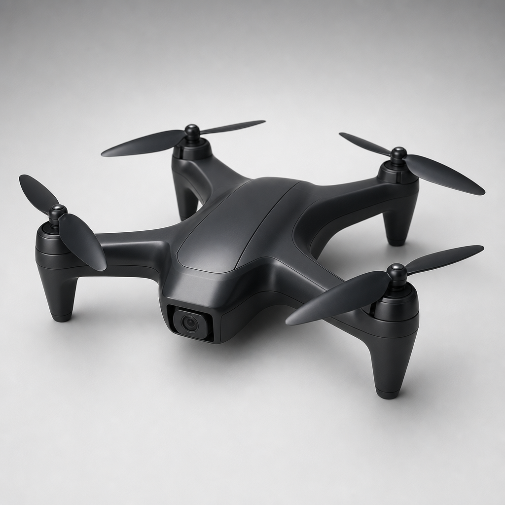
Plinth
H.Y.D.R.A. Hardened Quadcopter
## Prompt for Plinth Design and develop **H.Y.D.R.A., a Hardened Y Drone Reprogrammable Architecture**, as a quadcopter platform capable of maintaining controlled flight in environments affected by electromagnetic interference and intentional radio-frequency jamming. The project should address the vulnerability of conventional drones to signal interruption, stray electromagnetic fields, microwave interference, and deliberate communication jamming. The completed system should combine physical shielding, communication resilience, autonomous navigation, fault detection, and hardware redundancy so the aircraft can continue operating safely when one or more subsystems are disrupted. The proposed drone should include: * A quadcopter airframe with a hardened central electronics enclosure * RF-absorbing exterior coatings or equivalent electromagnetic attenuation materials * Copper shielding or conductive enclosures around sensitive electronics * Shielded wiring, grounded cable routing, filtered connectors, and protected power distribution * A flight controller capable of detecting failed or degraded sensors and components * Redundant critical hardware where practical * Frequency-hopping or otherwise resilient command-and-control communication * An onboard navigation system that can maintain flight when operator control is interrupted * Autonomous return, hold, land, or mission-continuation behaviors * Protection against electromagnetic interference reaching motors, electronic speed controllers, sensors, communication modules, and navigation electronics * Reprogrammable hardware and software architecture that supports future mission profiles and component upgrades * Logging and telemetry that record interference events, signal loss, system faults, and recovery actions The system should be designed to withstand realistic electromagnetic interference while remaining stable, controllable, repairable, and suitable for testing by a university engineering team. Do not assume the aircraft must defeat every form of military electronic warfare. Define a realistic and measurable interference environment based on sponsor requirements, available test equipment, regulatory limits, budget, and safety constraints. Develop the project as a complete engineering build plan. Include: 1. A clear problem statement and measurable system requirements 2. Defined interference scenarios, including expected frequencies, field strengths, distances, signal-loss durations, and test limitations 3. A system architecture covering the airframe, propulsion, power, shielding, communications, navigation, flight control, redundancy, and software 4. A preliminary drone layout with estimated dimensions, mass, payload capacity, center of gravity, and component placement 5. A mass budget and thrust-to-weight analysis 6. Motor, propeller, electronic speed controller, battery, and power-system selection 7. Estimated flight time under normal and hardened operating configurations 8. A shielding strategy using conductive enclosures, copper shielding, RF-absorbing material, filtering, grounding, and cable management 9. An explanation of how shielding effectiveness will be measured and validated 10. Communication options, including frequency hopping, spread-spectrum links, multi-band communication, and redundant radios 11. A navigation architecture that can continue operating during communication loss or degraded GPS 12. Candidate sensors such as dual IMUs, barometers, magnetometers, optical flow, visual odometry, radar, lidar, or inertial navigation 13. A fault-detection and isolation strategy for damaged, failed, or corrupted components 14. Hardware redundancy recommendations for critical flight systems 15. Software states for normal flight, degraded communication, navigation uncertainty, sensor disagreement, component failure, return-to-home, emergency landing, and mission abort 16. A secure and reprogrammable flight-software architecture 17. A complete bill of materials with commercially available components, quantities, approximate prices, vendors, and source links 18. Fabrication and assembly instructions 19. Wiring, grounding, shielding, and power-distribution diagrams 20. A software development plan with communication management, sensor fusion, fault detection, autonomous recovery, and event logging 21. A safe bench-test plan for individual components before flight testing 22. A staged flight-test plan that increases electromagnetic exposure gradually 23. A method for generating controlled and legally compliant interference during testing 24. Performance metrics such as packet loss, control latency, shielding attenuation, position error, attitude stability, recovery time, and successful mission completion 25. A hazard analysis covering propellers, batteries, electromagnetic exposure, unintended interference, flyaways, control loss, overheating, shielding shorts, and emergency procedures 26. Applicable aviation, radio-frequency, campus, and test-range restrictions that must be confirmed before testing 27. A project schedule, estimated labor, total budget, and recommended development phases 28. Alternative hardening concepts and an explanation of why the recommended design is preferred 29. Questions that must be answered by the sponsor before final engineering begins Organize the design into the following development phases: ### Phase 1: Baseline Aircraft Build and validate a conventional quadcopter with stable manual and autonomous flight. ### Phase 2: Physical Hardening Add conductive shielding, RF-absorbing materials, filtered power, protected wiring, and hardened enclosures. ### Phase 3: Communication Resilience Implement frequency-agile communication, redundant links, signal-quality monitoring, and automatic communication failover. ### Phase 4: Navigation Resilience Add onboard navigation capable of maintaining attitude, position, or safe recovery when external control or GPS is degraded. ### Phase 5: Fault Tolerance Add redundant sensors, fault detection, component-health monitoring, and degraded-operation modes. ### Phase 6: Controlled Interference Testing Test the system under progressively more challenging but safe and legally compliant electromagnetic conditions. Clearly separate: * Confirmed sponsor requirements * Engineering assumptions * Calculations * Recommended components * Experimental concepts * Regulatory constraints * Items requiring sponsor clarification Do not invent performance claims or describe the drone as fully jam-proof. Quantify the level of resilience that can realistically be demonstrated. Prioritize safe testing, lawful operation, measurable performance, modularity, and technical feasibility. The project summary on page 1 describes a quadcopter protected through RF-absorbing paint, copper shielding, hardware redundancy, frequency hopping, fault-aware flight control, and onboard navigation intended to reduce disruption when external controls are lost.
◢Bill of Materials
Flight Control & Compute
Flight controller, companion computer, dual IMUs, barometer, and magnetometer. Runs ArduPilot/PX4 for autonomous flight, sensor fusion, and fault detection.
Power
LiPo battery, power distribution, voltage regulation, filtering capacitors, and connectors that supply clean, stable power to all subsystems.
Rubycon 35PX1000MEFC10X20 Electrolytic Capacitor 1000µF 35V (Bulk Bypass / Power Filtering) – Qty 6
digikey
1189-1745-ND
AVATEC 100nF 50V X7R 0603 MLCC Bypass Capacitor (Decoupling on All Power Rails) – Qty 100
digikey
6547-AAGC18EX7R104KGNNTR-ND
Texas Instruments / Fairchild LM7805CT 5V 1.5A Linear Voltage Regulator TO-220 (5V Logic Rail)
digikey
2156-LM7805CT-ND
Navigation & Sensing
GPS/GNSS module, optical flow sensor, and secondary sensors for position hold and autonomous navigation during GPS or communication degradation.
SparkFun GPS Breakout – NEO-M9N, Qwiic, u.FL (Primary GNSS Module)
digikey
1568-15712-ND
u-blox NEO-M9N-00B M9 Standard Precision GNSS Module (Backup GNSS Chip, bare module for custom PCB)
digikey
672-NEO-M9N-00BTR-ND
Communication & RF Resilience
Frequency-hopping spread-spectrum RC link, redundant telemetry radio, and antenna hardware for resilient command-and-control.
EMI Shielding & Filtering
Copper tape shielding, ferrite cores, EMI filter capacitors, and RF-absorbing foam to harden the electronics enclosure against electromagnetic interference.
Parker Chomerics RF EMI Shielding Tape 54ft × 0.5in (Copper-Foil, Conductive Adhesive)
digikey
1944-CCH-18-101-0050-ND
Murata BLM18PG471SN1D Ferrite Bead 470Ω 0603 (EMI Filter on Power Lines) – Qty 50
digikey
490-5223-2-ND
Total: $273.72 USD
◢Build Schedule
14-week plan
All parts ordered; dev environment installed and verified on bench laptop
Place every component order immediately to account for lead times. The u-blox NEO-M9N-00B bare module and Parker Chomerics copper shielding tape are the longest-lead items (often 2-4 weeks from distributors like Mouser/DigiKey); order these first. Simultaneously install ArduPilot Mission Planner, PX4 Autopilot toolchain, Arduino IDE, and KiCad so the software environment is ready before hardware arrives.
Custom PCB submitted to fab; airframe received and dimensioned
Front-load the PCB order now to absorb the 2-3 week fabrication lead time. The custom PCB will carry the u-blox NEO-M9N-00B backup GNSS chip, Rubycon bulk capacitors, AVATEC MLCCs, Murata ferrite beads, and the LM7805CT regulator. While the PCB order is placed, perform a physical inventory of the airframe hardware and lay out a preliminary center-of-gravity diagram to confirm component placement before anything is bolted down.
You’ll need to know · 1
- Basic KiCad schematic and PCB layout
Airframe fully assembled; motors, ESCs, and props spun up on bench safely
Phase 1 begins: assemble the quadcopter airframe, mount brushless motors, wire ESCs to the power distribution board, and perform a propeller-off bench spin test to confirm motor direction and ESC calibration. This comes before any flight controller work because a mechanically sound, correctly spinning propulsion system is the prerequisite for all tuning that follows. Remove props during every bench electrical test.
You’ll need to know · 2
- Brushless motor and ESC theory - SparkFun Hobby Motor / ESC tutorial ↗
- LiPo battery safety and handling - Adafruit LiPo guide ↗
Flight controller configured; stable hover achieved in Stabilize mode
Mount and configure the flight controller running ArduPilot Copter, calibrate both IMUs, barometer, and magnetometer, then perform first outdoor hover in Stabilize mode with a safety pilot. This step establishes the baseline flight envelope before any hardening layers are added, making later A/B comparisons meaningful. Log all sensor data during hover for the Phase 6 baseline dataset.
You’ll need to know · 2
- ArduPilot/PX4 parameter configuration and calibration - ArduPilot Initial Setup Guide ↗
- RC transmitter/receiver binding and channel mapping
Autonomous loiter, RTL, and waypoint mission verified; baseline logs captured
Enable the SparkFun NEO-M9N Qwiic GPS, tune Loiter and AltHold modes, and fly a simple autonomous waypoint mission followed by a Return-to-Launch sequence. Capturing clean baseline telemetry logs now gives the team a quantified reference point — position error, attitude deviation, packet-loss rate — against which every hardening phase will be measured in Phase 6 testing.
You’ll need to know · 2
- GPS/GNSS module wiring and UART/I2C configuration - SparkFun GPS Basics ↗
- Mission Planner waypoint planning and flight modes
Custom PCB received, soldered, and bench-tested; power rails verified
The fabricated PCB returns this week. Solder the LM7805CT 5V regulator, all 100 AVATEC 100nF MLCC decoupling caps, all 50 Murata BLM18PG471SN1D ferrite beads, the six Rubycon 1000µF bulk capacitors, and the u-blox NEO-M9N-00B backup GNSS chip. Verify all power rails under load with a multimeter and oscilloscope before installing the board in the airframe, because a rework on the bench is far cheaper than a mid-flight power failure.
You’ll need to know · 2
- SMD and through-hole soldering - Adafruit Guide to Excellent Soldering ↗
- Oscilloscope use for power-rail ripple measurement
Copper shielding enclosure built; EMI attenuation measured on bench with SDR
Phase 2 begins: wrap the electronics enclosure with Parker Chomerics copper-foil shielding tape, install ferrite beads on all power and signal lines, apply RF-absorbing foam to interior surfaces, and route shielded cables with proper grounding. Use a software-defined radio (SDR dongle) and a signal generator or known interference source to make before/after field-strength measurements inside the enclosure — this produces the first quantitative shielding effectiveness data point required by the project spec.
You’ll need to know · 2
- EMI shielding and grounding fundamentals
- SDR receiver operation and spectrum analysis
FHSS RC link configured; redundant telemetry via Arduino Nano Every operational
Phase 3 begins: configure the frequency-hopping spread-spectrum RC link (e.g., ExpressLRS or TBS Crossfire on 900 MHz / 2.4 GHz) and integrate the Arduino Nano Every as a secondary telemetry and fault-log node that mirrors critical state over a separate serial channel. Program automatic failover logic so the Nano Every can command RTL if the primary link drops for more than a configurable threshold (default: 3 seconds). Test link switchover on the bench by physically blocking the primary antenna.
You’ll need to know · 2
- UART serial communication between microcontrollers - Arduino UART guide ↗
- Arduino IDE firmware development - Arduino Getting Started ↗
Arduino Uno R4 Minima logging firmware complete; dual-GPS failover bench-tested
Phase 4 begins: program the Arduino Uno R4 Minima as the companion logging MCU — it reads MAVLink telemetry, timestamps interference events, and logs signal-quality metrics to onboard flash/SD. Simultaneously configure ArduPilot's dual-GPS blending between the SparkFun NEO-M9N Qwiic (primary) and the NEO-M9N-00B on the custom PCB (secondary), then simulate primary GPS dropout on the bench by unplugging the Qwiic module and confirming the flight controller seamlessly switches to the backup. Dual-GPS failover must be verified before any GPS-degradation flight tests.
You’ll need to know · 2
- MAVLink protocol and parsing - ArduPilot MAVLink basics ↗
- I2C/SPI/UART sensor integration on Arduino
Fault-detection state machine validated; all failsafe modes bench-tested
Phase 5 begins: implement and test the full software state machine covering normal flight, degraded comms, GPS uncertainty, sensor disagreement, component failure, RTH, emergency land, and mission abort. Use ArduPilot's scripting (Lua) or companion-computer logic on the Uno R4 Minima to cross-check dual-IMU outputs, flag disagreements beyond a configurable threshold, and command the appropriate failsafe action. Simulate each fault condition on the bench using sensor disconnects and injected bad data before any of these states are trusted in the air.
You’ll need to know · 2
- State-machine design in embedded C++ or Lua
- ArduPilot failsafe parameter configuration - ArduPilot Failsafe docs ↗
HYDRA completes autonomous RTH after simulated GPS and RC dropout
Fly the fully hardened HYDRA airframe in a controlled outdoor area, deliberately inducing GPS dropout (by commanding GNSS_TYPE off via MAVLink) and RC link loss (by powering off the transmitter) while the aircraft is in Loiter, confirming autonomous RTH executes within the target recovery time. This is the first end-to-end integration flight and is deliberately done before formal interference testing so any integration bugs can be fixed in a zero-interference environment.
You’ll need to know · 2
- FAA Part 107 or recreational UAS operating rules
- Field safety observer procedures and emergency kill-switch use
All bugs triaged and resolved; shielding effectiveness re-confirmed on bench
Dedicated mid-project testing and debugging week. Review all data logs from Weeks 4–11, triage every open bug (ESC noise, GPS re-acquisition lag, failsafe timing, shielding gaps), and close or formally defer each item. Re-run the EMI attenuation bench test with the fully integrated enclosure to confirm shielding effectiveness hasn't degraded after integration. No new features are added this week — only fixes, tuning, and documentation of known limitations before Phase 6 interference testing begins.
You’ll need to know · 1
- Log analysis with Mission Planner or ArduPilot log tools - ArduPilot Log Analysis ↗
Controlled EMI tests complete; all performance metrics quantified and logged
Phase 6 controlled interference testing: using only legally compliant, Part 15-limited signal sources (e.g., a shielded anechoic box, attenuated signal generator, or campus EMC lab), progressively expose HYDRA to 2.4 GHz, 900 MHz, and broadband noise. Measure packet-loss rate, control latency, position error, attitude deviation, RTH trigger time, and shielding attenuation. All intentional RF emission must remain within FCC and campus safety limits; coordinate approvals with campus safety and FAA before this week begins.
You’ll need to know · 2
- FCC Part 15 and Part 97 limits for intentional emitters
- Spectrum analyzer and signal generator operation
Final demo flown; full technical report and hazard analysis submitted
Final two-week sprint concludes with a live demonstration flight showing normal operation, simulated link loss, autonomous RTH, and recovery — all in front of the sponsor and faculty. The deliverable package includes the full technical report (problem statement, architecture, BOM, shielding strategy, test results, and hazard analysis), all firmware source code in a version-controlled repository, wiring and grounding diagrams, a video recording of the demo, and a lessons-learned document with sponsor clarification items answered or escalated. All regulatory confirmations (FAA LAANC, campus UAS, FCC) must be on file before the demo flight.
You’ll need to know · 2
- Technical report writing and engineering documentation
- Git version control for firmware and hardware files
Generated by Plinth's AI agents. Verify before purchasing parts, following the schedule, or making safety-critical decisions.
Generated by Plinth - turn a project idea into a real buildable plan.